|
| | | |
How to change PCB Gerber file? Here is an example for adding a copper wire and a pad at the end of the new wire in the top layer. The drill file of the new hole will be generated accordingly, too.
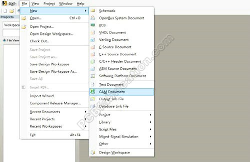
- Step 1: Open Altium Designer, create a new CAM file.
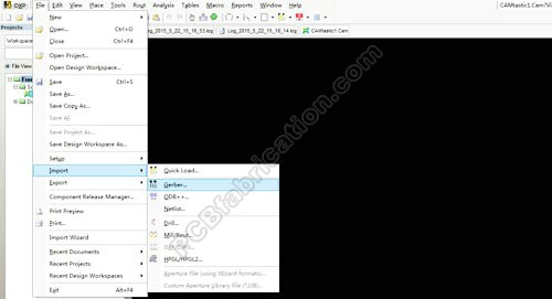
- Step 2: Import the original Gerber and drill files.
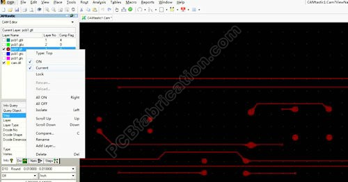
- Step 3: Set .GTL (Gerber Top Layer) to be current layer.
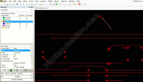
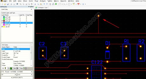
- Step 4: From menu Place, select flash to place a hole pad in the place in the PCB window.
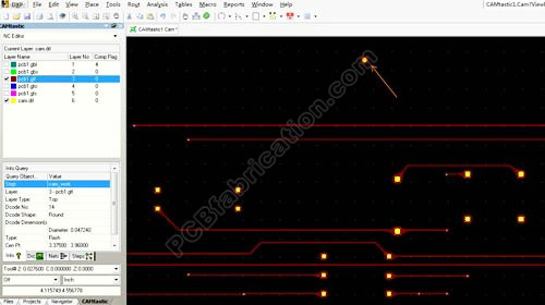
- Step 5: Switch to the Drill Hole window, and then change the CAM Editor to the NC Editor. Click to open the main menu Place to select Drill, and then click Drillpoint to add a drill hole into the center of the new pad.
- Step 6: Switch to CAM Editor again. Select .GTL layer. Click menu Place to add a line (copper wire) for the new pad to realize .
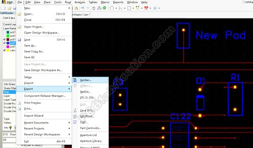
- Step 7: Export the new Gerber file for the new PCB fabrication.
|
|
|
|