
Countersink Holes in PCB
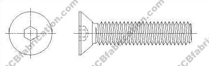
Countersink holes are tapered holes used for flat-head screws so the screw head can sit flush with the PCB surface or slightly recessed. In PCB fabrication, countersink machining normally applies to NPTH (Non-Plated Through Hole) features and requires attention to bevel angle, hole size, copper pullback, and board thickness.
What Are Countersink Holes in PCB?
A countersink hole is a conical opening machined at the top of a drilled hole. Its purpose is to match the tapered underside of a flat-head screw. When properly designed, the screw head sits flush with the board surface, which helps with enclosure fit, mechanical clearance, and finished appearance.
In PCB manufacturing, countersink holes are usually made as NPTH (Non-Plated Through Holes). This helps avoid electrical risk and simplifies machining control. If copper is too close to the bevel area, copper breakout or damage may happen during machining, so proper copper clearance must be reserved in the design.
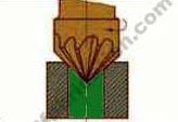
Countersink Hole Cross-Section Diagram
The diagram below shows a typical PCB countersink cross-section for a flat-head screw. It illustrates the head angle, NPTH hole, countersink major diameter, and recommended copper pullback area.

Note: This cross-section is a simplified engineering illustration for reference. Final dimensions should follow your screw datasheet and mechanical drawing.
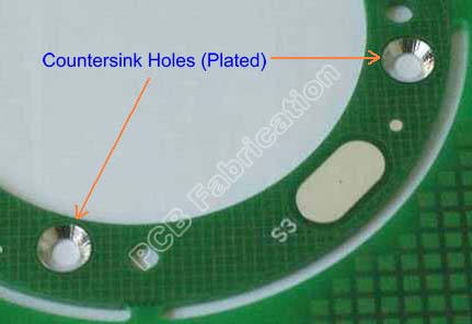
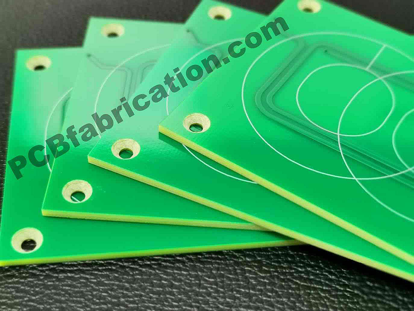
Countersink PCB Examples
Below are example images of countersink holes in PCB for flat-head screw applications.
Recommended Design Rules
| Parameter | Recommended | Notes |
|---|---|---|
| Hole Type | NPTH | Normally recommended for countersink machining |
| Bevel Angle | 82° or 90° | Must match your screw specification |
| Hole Diameter | Screw shank + clearance | Typical clearance: +0.10 to +0.20 mm |
| Countersink Depth | Based on screw head | Confirm by mechanical drawing or fastener datasheet |
| Copper Clearance | ≥ 0.50 mm | Helps avoid copper breakout during machining |
| Board Thickness | ≥ 1.6 mm recommended | Thinner boards need extra DFM review |
| Tolerance | Per drawing | Please specify if critical mechanical fit is required |
| Solder Mask on Bevel | No | Improves screw seating consistency |
82° vs 90° Countersink
| Item | 82° (Imperial) | 90° (Metric) |
|---|---|---|
| Typical usage | UNC / UNF flat-head screws | ISO metric flat-head screws |
| At same depth | Smaller countersink diameter | Larger countersink diameter |
| System mixing | Avoid mixing with 90° screws | Avoid mixing with 82° screws |
| Recommendation | Use when BOM is imperial | Use when BOM is metric |
Important: the countersink angle must match the screw head angle. Otherwise the contact is not full-face, and clamping force may be poor.
Common Flat-Head Screw Sizes (Reference Only)
| Fastener | Head Angle | Nominal Shank | Typical Head Ø | NPTH Hole (PCB) | CSK Ø (start) |
|---|---|---|---|---|---|
| M2 | 90° | 2.0 mm | ≈ 4.0 mm | 2.1–2.2 mm | ~4.0–4.5 mm |
| M3 | 90° | 3.0 mm | ≈ 6.0 mm | 3.1–3.2 mm | ~6.0–6.5 mm |
| M4 | 90° | 4.0 mm | ≈ 8.0 mm | 4.1–4.2 mm | ~8.0–8.5 mm |
| #4 | 82° | ~2.85 mm | ≈ 5.6 mm | 3.0–3.1 mm | ~5.6–6.0 mm |
| #6 | 82° | ~3.5 mm | ≈ 7.0 mm | 3.6–3.7 mm | ~7.0–7.5 mm |
| #8 | 82° | ~4.2 mm | ≈ 8.8 mm | 4.3–4.4 mm | ~8.8–9.3 mm |
Countersink Calculator
This simple calculator estimates recommended NPTH hole size and countersink major diameter.
Formula:
Dcsk = d + 2 × t × tan(θ / 2)
Mechanical & DFM Notes
- Confirm the screw head angle first. Do not mix 82° and 90°.
- Maintain copper pullback of at least 0.50 mm from the bevel edge.
- Normally no solder mask should remain on the chamfer surface.
- For thin PCB, review remaining material thickness carefully.
- If a countersink location is close to routing edge or slot, extra machining tolerance review may be needed.
- Please provide a mechanical drawing, marked-up PDF, or clear note in your design file or email.
How to Request Countersink PCB
If your PCB requires countersink holes, please clearly state the following information when sending your inquiry:
- Hole location
- Finished hole size
- Countersink angle: 82° or 90°
- Required countersink depth or matching screw model
- Board thickness
- Any required copper keep-out around the countersink area
Because our website does not support direct file upload, please email your Gerber files, drawing files, or marked PDF files to: [email protected] and [email protected]